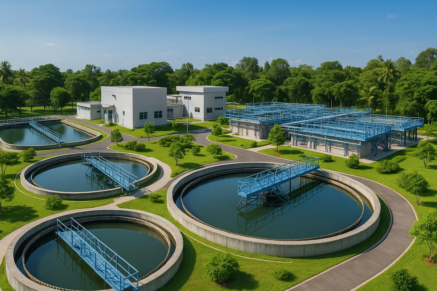
1. Context, Compliance Pressures, and Goals for Renovating Wastewater Treatment Systems in Seafood Processing
The seafood processing industry has a large discharge flow, fluctuating seasonally and according to product structure, with high organic matter, oil, and microbial content. This causes the input loads of BOD, COD, SS, N, P, and Coliform to always fluctuate and can spike after each cleaning shift. If the biological cluster and pre-treatment are not optimized, the system is very likely to fluctuate, produce odors, have poor settling sludge, high operational costs, and a risk of violating discharge standards.
Legally, the specialized standard applied to wastewater from seafood processing is QCVN 11-MT:2015/BTNMT. This standard specifies the maximum allowable values for parameters when discharged into receiving sources in a formula that considers the receiving source coefficient and discharge flow (Kq, Kf). This means that the discharge threshold depends not only on the nominal “C” but also on the scale of the facility and the characteristics of the water body. When renovating the system, businesses should design according to a stricter scenario (unfavorable Kq, Kf) to have a safety margin, especially during peak capacity phases.
The technological goal in renovation is to enhance the stability and efficiency of the biological mass for high organic and nutrient loads, while simultaneously reducing energy costs through the rational arrangement of anaerobic – anoxic – aerobic zones and optimizing pre-treatment (fat separation, flotation). The renovated system needs to be flexible in response to load fluctuations, maintain DO, MLSS, and reasonable sludge circulation, while also effectively controlling disinfection to meet microbial limits as required by the receiving source.

2. Characteristics of Seafood Processing Wastewater and Load Fluctuations: Actual Data
This industry’s wastewater consists of main streams: from the processing area (raw material washing, filleting, sizing, freezing), cleaning of the workshop – equipment, water from the washing system, and domestic wastewater. It is characterized by high oil and grease, by-products (bones, scales, organs), color – odor from blood, protein, along with significant nitrogen and phosphorus content. The organic distribution ratio usually includes soluble and insoluble parts; actual data records about 30 – 40% of organic matter in soluble form and 60 – 70% in insoluble form, emphasizing the crucial role of mechanical pre-treatment – flotation before biological treatment.
Field analysis data show that the input pollution levels can be very high and vary widely. One reference source recorded COD in the range of 500 – 600 mg/L, BOD fluctuating widely from 400 – 3200 mg/L, TSS from 128 – 420 mg/L, total nitrogen from 58 – 120 mg/L, total phosphorus from 12 – 90 mg/L, and total Coliform around 10^4 – 10^5 MPN/100 mL. These figures explain why facilities often experience biological overload during “shock load” events (especially after cleaning shifts), if the pre-treatment – equalization and biological clusters do not have sufficient margins.
In another practical operating system, repeated sampling results showed deep treatment capability when the line was organized rationally: input COD 1600 – 1775 mg/L, output 20 – 32 mg/L; input BOD 1491 – 1728 mg/L, output 11 – 30 mg/L; SS from 456 – 494 mg/L, output 4 – 8 mg/L; total phosphorus from 27.5 – 52.3 mg/L, output 3 – 10 mg/L. Input ammonia from 24.7 – 35.9 mg/L can be reduced to 8 – 25 mg/L depending on conditions. Total Coliform decreased to levels of 360 – 2600 MPN/100 mL. These results demonstrate the role of coordinated biological mass (anaerobic – anoxic – aerobic) along with good pre-treatment and proper disinfection to stabilize the effluent quality.
3. Optimal Biotechnological Configuration for Renovation
3.1. Pre-treatment: Screening, Oil Separation, Flotation, and Equalization
In practice, the pre-treatment cluster is the “lever point” to reduce shock for the biological system. Bar screens and fine screens remove large debris to protect pumps and pipes. Oil separation tanks are mandatory because animal fats cause adhesion, clogging of equipment, and inhibition of microorganisms. For plants with high flow and FOG content, adding dissolved air flotation (DAF) immediately after oil separation will collect additional residual oil and difficult-to-settle solids, reducing insoluble organic loads for downstream tanks. This step is crucial to prevent floating sludge, foaming, and odors in the aerobic biological mass.
The equalization tank serves to smooth out flow and pollutant concentration, while also adjusting pH – mixing to ensure stable biological input. Experience shows that when pre-treatment and equalization operate well, the biological mass encounters fewer “shock loads,” significantly reducing DO fluctuations and limiting sludge washout. This also directly impacts costs, as the aerobic cluster will require less energy when peak loads are “flattened.”
3.2. Anaerobic Cluster (UASB) for High Organic Loads
UASB (Upflow Anaerobic Sludge Blanket) is often seen as the ideal biological “shock absorber” for protein and fat-rich seafood wastewater. Here, anaerobic microorganisms decompose organic matter into biogas and simple inorganic substances through hydrolysis, acidification, acetate formation, and methanogenesis. With wastewater having high COD/BOD and many insoluble parts, UASB significantly reduces COD/BOD loads before entering the aerobic mass, while also decreasing oxygen demand and aerobic sludge production.
Actual data record that COD/BOD removal efficiency in the anaerobic mass can reach about 60 – 80% if operating conditions are stable. However, for UASB to work effectively, good pre-treatment (reducing fats and large SS) must be ensured, along with controlling foam – scum, evenly distributing flow, and maintaining sludge granule structure. If fat scum accumulates or the three-phase separation area is ineffective, sludge washout and large fluctuations will occur in downstream processes. In renovation, adding a three-phase settling plate, optimizing gas collection, and regularly maintaining the scum collection structure are low-cost interventions that significantly improve stability.
3.3. Anoxic – Aerobic Cluster (Anoxic – Aerotank) for N, P Removal and Deep Clarification
After anaerobic treatment, the anoxic – aerobic cluster is the “heart” of biological optimization for seafood wastewater. In the aerobic phase (Aerotank), microorganisms oxidize remaining organic matter to CO₂ and H₂O while performing ammonium nitrification. To ensure sustainable microbial populations, DO in the aerobic tank should be maintained in the range of 2 – 4 mg/L; this DO range is practical for balancing sufficient oxygen requirements without wasting aeration energy. Activated sludge should be maintained at an MLSS concentration of about 1,000 – 3,000 mg/L, with a characteristic organic load for Aerotank of about 0.32 – 0.64 kg BOD/m³.day depending on configuration and effluent goals.
Regarding nitrogen metabolism, the nitrification process converting ammonium to nitrate occurs effectively when DO is maintained within the specified range; each 1 g of ammonium nitrogen requires about 3.96 g of oxygen for complete oxidation. Combining the nitrate recycle stream back to the anoxic tank will facilitate the denitrification process to nitrogen gas, reducing total N in the effluent and limiting the phenomenon of eutrophication in the receiving source. With the characteristic of seafood wastewater having significant total P, the alternating anoxic – aerobic cycles also support the metabolism and absorption of P in the activated sludge. To operate Aerotank efficiently, using fine bubble diffusers with sizes below 10 µm helps enhance oxygen transfer efficiency, thereby reducing the required blower capacity.
3.4. Biological Settling, Intermediate Storage – Disinfection and Microbial Control
The water after the Aerotank flows to the settling tank to separate biological flocs by gravity; settled sludge is recycled back to the aerobic and anoxic tanks to maintain concentration, while excess is sent for sludge treatment. Settling quality depends heavily on the F/M balance, floc structure, and surface loading; when sludge settles poorly or foams, it is often necessary to review the load, DO, incoming oil and grease, and the recycling ratio. Arranging a short-term intermediate storage tank after settling helps “buffer” before disinfection, while also facilitating the further separation of small suspended flocs.
The disinfection stage typically uses chlorine to control Coliform and pathogens. In practice, total Coliform after treatment can be reduced to a few hundred to a few thousand MPN/100 mL when the pre-treatment – biological – settling line operates stably and the chlorine dose is appropriately controlled. Note that residual chlorine if it backflows into the biological cluster can inhibit microorganisms, reducing treatment efficiency. Therefore, it is advisable to arrange dosing points, mixing, and controlling residual chlorine appropriately to achieve microbial goals while preserving the biological microbial system.
4. Comparison Table of Input/Output Data and Core Biological Parameters
The table below summarizes actual data before and after treatment in a seafood processing wastewater system, along with a reference table of important biological operating parameters commonly used during renovation. The figures are real data from specialized documents.
| Parameter | Input (value range) | Output (value range) | Treatment Efficiency (%) |
|---|---|---|---|
| pH | 7.1 – 7.1 | 7.6 – 7.7 | - |
| SS (mg/L) | 456 – 494 | 4 – 8 | 98 – 99 |
| COD (mg/L) | 1600 – 1775 | 20 – 32 | 98 – 99 |
| BOD5 (mg/L) | 1491 – 1728 | 11 – 30 | 98 – 99 |
| Ammonia (mg/L) | 24.7 – 35.9 | 8 – 25 | 28 – 48 |
| Total Phosphorus (mg/L) | 27.5 – 52.3 | 3 – 10 | 64 – 94 |
| Total Coliform (MPN/100 mL) | 1.5×10^6 – 2.4×10^6 | 360 – 2600 | - |
The core biological parameters used to adjust operations after renovation:
| Item | Reference Value | Operational Notes |
|---|---|---|
| COD/BOD Removal Efficiency in Anaerobic | ~60 – 80% | Depends on pre-treatment and stability of UASB granule layer |
| DO in Aerotank | 2 – 4 mg/L | Maintain DO within this range to balance performance/electricity consumption |
| MLSS in Aerotank | 1,000 – 3,000 mg/L | Adjust sludge recycling to maintain target range |
| Organic Load Aerotank | 0.32 – 0.64 kg BOD/m³.day | Based on flow rate and effluent goals |
| O₂ Demand for 1 g N–NH₃ | ~3.96 g O₂ | Calculated for ammonium nitrification demand |
| Bubble Size (Diffuser) | < 10 µm | Improves oxygen transfer efficiency |
5. Common Operational Errors in Seafood Wastewater Treatment and Solutions
First, “overlooking” oil and grease at the source is a common mistake. When the oil separation tank is ineffective or DAF operates poorly (lack of scum scraping, inappropriate coagulant chemicals), oil and grease will go directly into the biological treatment causing adhesion, persistent white foam, floating sludge in settling, and DO fluctuations due to the foam surface hindering mass transfer. Solutions include optimizing oil separation (adjusting retention time, scum collection), calibrating DAF (equalizing flow, selecting appropriate chemical doses), and regularly cleaning pipes – tank surfaces.
Second, unstable DO in the Aerotank. Below 2 mg/L, the organic decomposition process and particularly nitrification are impaired; above 4 mg/L, it neither significantly improves performance nor increases energy consumption. It is necessary to install and calibrate blower control based on DO, distribute air evenly, and regularly check for clogging in the diffuser. During peak load phases, gradually push MLSS to the range of 1,000 – 3,000 mg/L to have a biomass “buffer,” while maintaining DO in the range of 2 – 4 mg/L as a reference.
Third, chlorine shock from cleaning areas. Residual chlorine entering pre-treatment – equalization can cause mass microbial death, indicated by chlorine odor, foam, and rapid COD/BOD performance drop. The solution is to separate the washdown – CIP stream to an intermediate neutralization/chlorine removal tank before mixing with the main stream; control the location and dosing of chlorine in the disinfection tank; and regularly monitor residual chlorine to avoid “overdosing.”
Fourth, poor settling sludge and floating sludge in the settling tank due to F/M imbalance or denitrification in the settling zone. Sudden organic loads or lack of oxygen in the near-settling zone cause gas generation that makes sludge float. It is necessary to enhance equalization, review the nitrate recycling loop from aerobic to anoxic to limit nitrates moving to the settling tank, adjust the sludge recycling ratio, and control DO exiting the Aerotank appropriately. In the long term, adding a clear anoxic compartment and optimizing flow distribution helps limit recurrence.
Fifth, unstable disinfection. When chlorine dosing is too low, Coliform increases; when too high, residual chlorine occurs in the effluent and risks affecting microorganisms if recycled. Therefore, it is essential to control water quality before disinfection (low turbidity helps chlorine work more effectively), the dosing and mixing points of chemicals, along with monitoring residual chlorine at the effluent tank to achieve microbial goals while ensuring safety for the system.
6. Strategies to Optimize Investment (CAPEX) and Operational (OPEX) Costs When Upgrading Systems
With organic and oil-rich seafood wastewater, energy costs in the aerobic zone can easily become a “hot spot.” By placing anaerobic (UASB) upfront, most COD/BOD is removed under non-aeration conditions, thereby significantly reducing oxygen load in the Aerotank. Good pre-treatment (fat separation + DAF) not only stabilizes the biological system but also saves on polymer, prevents pipe clogging, and reduces cleaning costs – these are “hidden” operational expenses that accumulate significantly over time.
During the renovation phase, priority should be given to high cost/effectiveness “leverage” items: replacing – adding fine bubble diffusers to increase oxygen transfer; restructuring the sludge – nitrate recycling pipes to utilize nitrogen removal; arranging intermediate/equalization tanks reasonably to reduce shock loads; installing DO sensors at key locations to control blowers based on actual needs. This approach allows for reduced energy consumption without having to expand the area excessively.
OPEX, besides aeration electricity, also includes flotation – disinfection chemicals, sludge removal – treatment costs, and labor/supervision. Reducing SS and oil and grease at the source will directly decrease the chemical doses needed for DAF, reducing the generation of both chemical and biological sludge. In disinfection, optimizing water quality before disinfection helps reduce chlorine doses while limiting residual chlorine in the effluent. Regarding labor, automating DO measurement – control and critical tank levels helps reduce manual operations and operational errors due to intuition.
7. Renovation Roadmap for Existing Systems: From Diagnosis to Stable Operation
The first step is diagnosis through data. Businesses should conduct multiple sampling rounds according to production shifts to clearly identify the fluctuation ranges of COD, BOD, SS, N, P, and Coliform; separately recording cleaning rounds to observe the level of input “shock.” Concurrently, assess the current state of pre-treatment (oil and grease levels, DAF efficiency) and core biological indicators such as DO in the Aerotank, MLSS, floc status, and settling quality. This data serves as the foundation for designing renovation packages based on specific bottlenecks rather than mechanically expanding indiscriminately.
The next step is to design configurations and prioritize interventions. For systems that already have an Aerotank and settling tank but frequently experience overload, consider adding UASB upfront to reduce organic loads, while also rearranging a proper anoxic compartment for effective nitrogen removal. In the Aerotank, set DO targets of 2 – 4 mg/L and gradually raise MLSS to the range of 1,000 – 3,000 mg/L through sludge recycling control. For pre-treatment, standardize the operation of fat separation and DAF to reduce SS and FOG entering biological treatment. All adjustments should be tested step by step and closely monitored to ensure the microbial system adapts safely.
The fine-tuning operational phase focuses on long-term stability. Establish standard procedures for seasonal peak load situations, processing procedures when DO deviates from target ranges, when foam/floating sludge appears, or when Coliform increases. Maintain a maintenance schedule for blowers, diffuser plates, and DAF structures; train personnel to early identify signs of “chlorine shock.” Finally, align operational goals with the compliance framework of QCVN 11-MT:2015/BTNMT and the characteristics of the receiving source (Kq, Kf) to periodically review the ability to meet various operational scenarios.
8. Conclusion
For seafood processing wastewater, optimizing biological technology is not just about expanding tanks but reorganizing the “value chain” from pre-treatment to anaerobic – anoxic – aerobic treatment and disinfection. Actual data show that when these links are connected correctly, SS, COD, and BOD can be significantly reduced, N and P are controlled, and Coliform decreases markedly. The technical focus lies in reducing oil and grease at the source, maintaining DO at 2 – 4 mg/L, keeping MLSS within an appropriate range, and smartly controlling chlorine to achieve microbial goals while preserving the biological microbial system.
Regarding compliance, QCVN 11-MT:2015/BTNMT is the foundational standard for seafood processing wastewater. Since the allowable thresholds depend on Kq and Kf, businesses need to design – operate within safety margins, especially during peak production periods. When renovations are planned and data-driven, the system increases stability while sustainably reducing operational costs, thereby enhancing the capacity to meet the development needs of the plant without compromising environmental risks.
FAQ
-
What makes seafood wastewater “more difficult” than other food industries?
It contains more oil, grease, protein, and pathogens, and fluctuates significantly according to production shifts and equipment cleaning. Actual data show that BOD can range from several hundred to over a thousand mg/L, along with significant N, P, and Coliform, requiring pre-treatment and biological processes to be very stable.
-
Why should UASB be placed before Aerotank during renovation?
UASB helps early cut COD/BOD loads (about 60 – 80% under stable conditions), significantly reducing oxygen demand in the Aerotank and aerobic sludge production. This not only increases safety margins for biology but also reduces long-term energy consumption.
-
What DO level is appropriate for the Aerotank treating seafood wastewater?
A DO range of 2 – 4 mg/L has been recorded as suitable to balance oxidation – nitrification performance with energy costs. Below 2 mg/L often impairs the process, while above 4 mg/L does not yield proportional treatment benefits but increases energy consumption.
-
How to reduce Coliform in the effluent without “killing” microorganisms in the biological tank?
Optimize water quality before disinfection (low turbidity, low SS) to enhance chlorine effectiveness, along with appropriately arranging dosing points – mixing and monitoring residual chlorine at the effluent tank. Avoid allowing chlorine to backflow into the biological treatment causing microbial inhibition.
-
What core biological indicators should be monitored after renovation?
DO in the Aerotank (2 – 4 mg/L), MLSS concentration (1,000 – 3,000 mg/L), settling quality and floc status, along with anaerobic mass efficiency. These are the “knobs” that directly affect performance and operational costs.
-
Which standard applies specifically to seafood processing wastewater?
QCVN 11-MT:2015/BTNMT is the specialized standard for seafood processing wastewater. It specifies the maximum allowable values according to a formula that considers the receiving source coefficient (Kq) and discharge flow (Kf), so design – operation must take these coefficients into account.
Nanoen
NANO THANG LONG ENVIRONMENT COMPANY LIMITED
Hanoi Office: No. 15 TT18 Van Phu Urban Area, Ha Dong, Hanoi
Can Tho Office: 661E/29, Vo Van Kiet Street, Binh Yen A Area, Long Hoa Ward, Binh Thuy District, Can Tho City
Ho Chi Minh City Office: 533/12/7, Pham Van Bach Street, Ward 15, Tan Binh District, Ho Chi Minh City
Hotline: 0986.689.781 - 0969.054.226
Email: thanglongnanoen@gmail.com
Facebook: www.facebook.com/thanglongnanoen