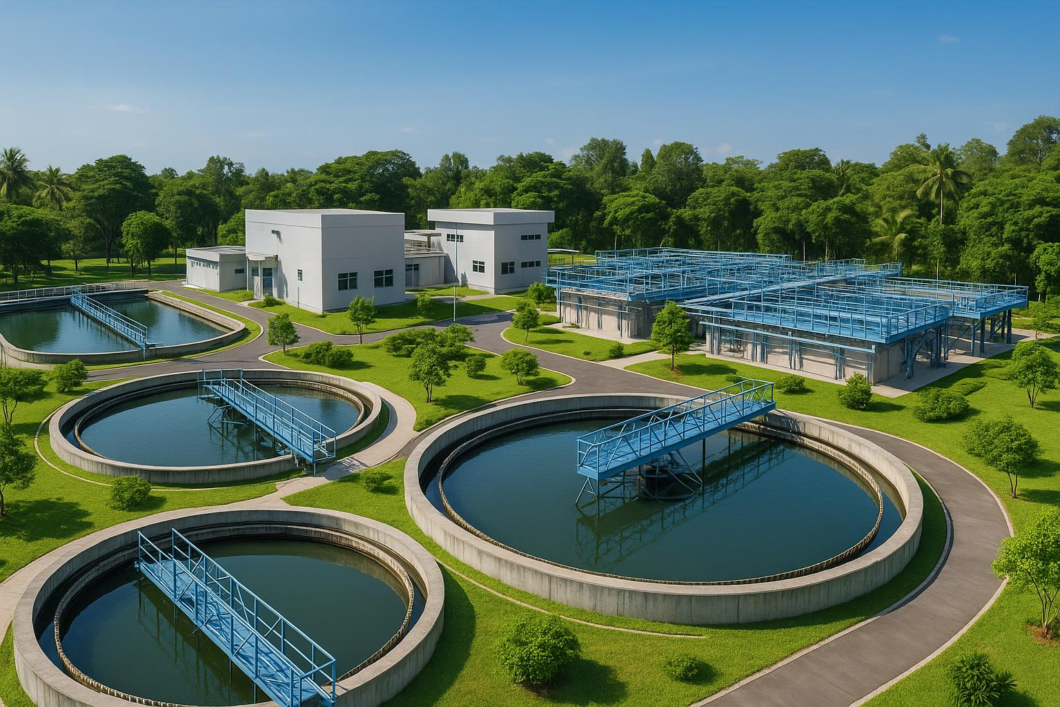
1. Context and Operational Pressures of Domestic Wastewater Systems in Hospitals
Within the hospital premises, domestic wastewater comes from inpatient, outpatient, administrative areas, laundry, cafeteria kitchens, etc., with flow rates and compositions varying by season, day, and shift. As services, bed numbers, and operational capacity expand, the domestic wastewater treatment system frequently faces the risk of overload. Additionally, modern healthcare facilities have many specific waste streams (from laboratories, disinfection, instrument sanitation, etc.), complicating the stability of the input. Therefore, proactively identifying early signs of overload and implementing modular renovation plans without interrupting operations is a crucial requirement in hospital management.
The health management agency has emphasized the need to enhance waste management within healthcare facilities, requiring units to assess the current situation, prioritize budget allocation for upgrading or renovating overloaded or degraded systems; while also strengthening operational monitoring and wastewater monitoring after treatment to ensure compliance with environmental technical standards before discharge. This necessitates hospitals and clinics to have a systematic renovation plan based on data and technology options that suit the actual site, waste streams, and operational workforce.
In the following section, the article focuses on domestic wastewater within the hospital premises, using a reference technology model published for a scale of 110 m3/day to analyze how to identify overload, key renovation steps, essential investment items, and common operational errors. The goal is to provide a feasible roadmap that can be implemented in phases, ensuring the system operates stably, safely, and meets current management requirements.

2. Signs of Overload or Degradation in Domestic Wastewater Systems
When the domestic wastewater treatment system is overloaded, "surface" phenomena usually appear first. Unpleasant odors emanating from the collection pit, equalization tank, or overflow area are typical indicators of unintended anaerobic decomposition, often occurring when retention time is uncontrolled or aeration and mixing are insufficient. Thick foam, sludge accumulation, and spikes in output turbidity are also signs that the microbial mass in the biological tank is shocked or overloaded according to shift changes, surgical shifts, or peak hours in the cafeteria.
At the equipment level, overload is often reflected in the frequency of protective activation of pumps, blowers, and multiple high water level alarms at the equalization tank. Operators may notice that pumps have to work continuously beyond normal thresholds, valves and pipes exhibit shaking during shift changes, and there may even be "back pressure" phenomena at some collection points. If the system has a filtration stage, rapid fouling of the membrane, the need for more frequent membrane cleaning, and increased suction pressure are signs of overload or insufficient pretreatment.
Hospital management can also recognize "slow signs" through increased operational costs due to high electricity consumption for mixing, aeration, and washing; escalating disinfection chemical costs due to increased dosing to compensate for fluctuations in waste streams; along with higher-than-expected maintenance requirements. These indicators, combined with feedback from the infection control department regarding odors and sanitary conditions in the treatment area, provide the basis for concluding that the system needs upgrading.
3. Comprehensive Renovation Plan: From Local Upgrades to Technology Adjustments
3.1. Reviewing the Current Situation and Modular Renovation Strategy
The first stage of any renovation project is to review each step in the treatment chain: collection – pretreatment – equalization – anaerobic/aerobic – sludge separation – disinfection – discharge. The most suitable strategy for hospitals is modular renovation, minimizing system downtime. Specifically, the collection pit and equalization tank can be reinforced or expanded, followed by adding anaerobic/aerobic stages if lacking; finally, integrating a membrane filtration module to stabilize output when organic and microbial loads fluctuate.
The modular approach helps address "bottlenecks" at upstream choke points (e.g., equalizing flow and pollutant concentration) rather than increasing capacity simultaneously, which can be costly. With the treatment area adjacent to functional areas, adding disinfection and submerged membrane filtration items is advantageous as it utilizes good space, reducing the need for large settling tanks. The ultimate goal is to bring domestic waste streams back to a stable state, reduce shock loads for aerobic biology, and control the risk of pathogenic microorganisms before discharge.
3.2. Adding Pretreatment: Three-Compartment Septic Tank and Cafeteria Grease Separation
For domestic wastewater, a three-compartment septic tank plays an important pretreatment role. The three-compartment configuration supports settling solids, partially anaerobic decomposition of organic matter, and preliminary filtration before water enters the central treatment system. During a retention period of 6–8 months, fresh sludge in the septic tank decomposes, generating gas and reducing volume, helping to limit the organic load entering the subsequent biological stage. Although it cannot replace centralized treatment, a properly functioning septic tank will significantly reduce input fluctuations.
Simultaneously, cafeteria wastewater needs to be separated for grease before entering the common stream. The grease separation stage removes oils and fats, which are factors causing sludge washout, reducing aeration efficiency and adhering to the membrane surface if membrane integration is present. Placing the grease separation unit close to the source and maintaining regular cleaning helps reduce operational loads for the entire downstream system, especially when the hospital has a large food service scale.
3.3. Stabilizing Flow and Load: Collection Pit, Equalization Tank with Aeration
The collection pit is the point where wastewater concentrates before being pumped to the next stage. Here, coarse screens need to be installed to remove large debris, preventing clogging of pumps and downstream equipment. For a scale of approximately 110 m3/day, a reinforced concrete collection pit can be arranged with dimensions of about 2 m long, 1 m wide, and 2.5 m high, corresponding to a volume of about 5 m3, to temporarily hold and limit odor generation due to anaerobic conditions at the collection point.
The equalization tank is the "heart" of the stabilization stage, serving to flatten fluctuations in flow and concentration of pollutants. With the reference model, the reinforced concrete equalization tank has dimensions of 2.4 m long, 2.4 m wide, and 4 m high, with a volume of approximately 23.04 m3. The tank is equipped with an aeration system to ensure even mixing, prevent localized settling, and limit odor generation. This design helps prevent the microbial mass downstream from being "shocked," while also allowing for more stable water pumping programming rather than running according to sudden discharge bursts.
3.4. Nitrogen Removal and Aerobic Biological Treatment: Anaerobic – Aerobic
To control nitrogen-containing compounds in domestic wastewater, an anaerobic (anoxic) biological treatment configuration combined with aerobic treatment is often applied. In the anaerobic phase, denitrifying microorganisms use remaining carbon sources to remove nitrogen in oxidized form; in the aerobic phase, aerobic microorganisms decompose dissolved organic matter and oxidize ammonia. For the reference scale, the anaerobic tank can be arranged to be 3.5 m long, 2.6 m wide, and 5 m high, with a volume of approximately 45.5 m3; the aerobic tank is 2.5 m long, 2.6 m wide, and 5 m high, with a volume of about 32.5 m3.
During renovation, it is essential to ensure adequate mixing in the anaerobic phase to maintain microbial-substrate contact, as well as sufficient aeration intensity in the aerobic tank to support decomposition and control odors. If the existing system already has a biological tank, expanding the volume, improving air distribution, and adding a sludge recirculation pump are core upgrade steps that enhance efficiency without needing to change the entire technology.
3.5. Enhanced Sludge Separation and Disinfection Using MBR and Javen Membrane Modules
In many hospital projects, sludge separation through gravity settling is at risk of fluctuations due to loading and surfactants from domestic activities. Integrating submerged MBR membrane modules in the activated sludge tank allows for improved liquid-solid phase separation quality. The membrane has very small pore sizes, ranging from 0.04–0.4 µm, capable of retaining colloids, bacteria, viruses, and suspended solids; the permeate passes through the membrane and moves to the disinfection stage. Using membrane materials like PVDF and maintaining regular membrane cleaning helps stabilize permeate flow during load fluctuations.
The post-membrane disinfection stage typically uses Javen solution. In the reference model, the system is arranged with a disinfection solution tank of approximately 1 m3 to proactively supply chemicals, along with a separate tank of about 2 m3 for membrane cleaning. After disinfection, the water can be passed through a pressure filter tank before being discharged into the receiving source. This design helps enhance microbiological safety and creates a "buffer" for controlling when the input fluctuates significantly, especially during peak healthcare periods.
3.6. Renovation Scenario for a Capacity of Approximately 110 m3/day
With a scale of approximately 110 m3/day, the reference technology chain includes: collection pit – equalization tank – anaerobic tank – aerobic tank – MBR module – intermediate tank – pressure filtration – disinfection – discharge. This configuration has taken into account the specific characteristics of domestic wastewater in healthcare premises, which contain many organic substances, nutrients, suspended solids, and pathogenic microorganisms. By separating anaerobic/aerobic phases and using MBR, the system increases the ability to retain sludge, stabilizes solid separation efficiency, and supports the subsequent disinfection stage.
For reinforced concrete structures, items can be arranged according to reference dimensions/volumes as follows: collection pit approximately 5 m3, equalization tank approximately 23.04 m3, anaerobic tank approximately 45.5 m3, aerobic tank approximately 32.5 m3, intermediate tank approximately 38.4 m3, sludge tank approximately 10.8 m3. Two plastic tanks for chemical storage include a disinfection solution tank of approximately 1 m3 and a membrane cleaning tank of approximately 2 m3. These parameters help the design team make preliminary estimates, define the renovation scope, and prepare construction plans to minimize operational disruptions.
| Criteria | Typical Overload Status | Reference Renovation Plan ~110 m3/day |
|---|---|---|
| Collection & Pretreatment | Insufficient coarse screens, ineffective grease separation; septic tank operates poorly. | Coarse screens at the collection pit; separate grease separation for the cafeteria; three-compartment septic tank operates stably in a 6–8 month cycle. |
| Flow Equalization | Lack of equalization tank or small volume, prone to shock loading in the biological tank. | Reinforced concrete equalization tank ~23.04 m3, continuous aeration and mixing. |
| Biological Treatment | Single aerobic tank, lacking nitrogen removal; unstable settling. | Anaerobic (anoxic) ~45.5 m3 + aerobic ~32.5 m3; sludge recirculation; optimized air distribution. |
| Sludge Separation & Quality Enhancement | Secondary settling fluctuates, sludge washout during peak hours. | Submerged MBR (pore size 0.04–0.4 µm), intermediate tank ~38.4 m3; pressure filtration. |
| Disinfection | Fluctuating disinfection doses, difficult to control when output is turbid. | Using Javen with a storage tank ~1 m3; membrane cleaning with a tank ~2 m3; stabilizing microbiology after MBR. |
| Main Equipment | Pumps and blowers operating under overload, repeated high water level alarms. | Submersible pumps for equalization ~2.2 kW (2 units), surface blowers ~5.5 kW (2 units), sludge pumps ~1.5 kW (2 units), membrane suction pumps ~2 kW. |
4. Technical and Operational Parameters Reference for the 110 m3/day Model
To visualize the equipment requirements and parameters, one can refer to the machinery list of a wastewater treatment system for a hospital with a scale of approximately 110 m3/day. In the equalization tank, use submersible pumps with a capacity of about 2.2 kW, arranging 2 pumps for alternating backup, ensuring proactive water supply to the subsequent stages at a more stable rhythm. The aerobic tank is equipped with submersible pumps of 1.5 kW (2 units) to support flow recirculation/local coordination and prevent localized settling. Surface blowers of approximately 5.5 kW (2 units) supply air to the aeration area, combined with 22 air distribution discs to ensure even distribution and reduce dead zones.
The MBR membrane module uses a suction pump with a capacity of approximately 2 kW to extract water through the membrane, along with a chemical dosing pump (about 1/3 HP) for disinfection and a membrane cleaning pump (about 1/3 HP) for periodic cleaning operations. In the anaerobic area, a submersible mixer with a capacity of approximately 2 kW is arranged to maintain sludge suspension, prevent settling, and enhance microbial contact with substrates. These power parameters provide a preliminary basis for calculating electrical loads, scheduling operations by shifts, and arranging reasonable backups.
Regarding the structure, the main tanks such as collection, equalization, anaerobic, aerobic, intermediate, and sludge storage have specific reference dimensions, allowing the project team to check the density of equipment installation, operational workspace, and access routes for maintenance needs. For example, a sludge storage tank with a volume of approximately 10.8 m3 allows for receiving sludge captured at the membrane and excess sludge from aerobic biological treatment before transferring according to internal procedures. The control room can be built with brick walls and a corrugated roof, with dimensions of about 3 m long, 2.5 m wide, and 3.7 m high to protect electrical cabinets, blowers, and important accessories from rain and sunlight.
The technology chain ends with disinfection using Javen, ensuring the inactivation of pathogenic microorganisms before discharge into the receiving source. When operating the membrane module, periodic membrane cleaning with a specialized solution stored in a tank of approximately 2 m3 and supplied through a dedicated cleaning pump is an essential operation to maintain stable permeate flow. At the end of the chain, a pressure filter tank helps "polish" water quality, reducing remaining turbidity, creating a safety margin for the discharge phase, especially useful when the input flow fluctuates during peak hours.
| Equipment | Function | Quantity | Reference Parameters |
|---|---|---|---|
| MBR Membrane Module (PVDF) | Separating water from activated sludge mixture | 1 system | Pore size ~0.04–0.4 µm |
| Submersible Pump for Equalization Tank | Pumping wastewater to subsequent stages | 2 units | ~2.2 kW |
| Submersible Pump for Aerobic Tank | Flow coordination/local recirculation | 2 units | ~1.5 kW |
| Sludge Recirculation Pump | Recirculating activated sludge | 2 units | ~1.5 kW |
| Surface Blower | Supplying air for aeration tank | 2 units | ~5.5 kW |
| Submersible Mixer | Mixing in the anaerobic tank | 1 unit | ~2 kW |
| Membrane Suction Pump | Extracting water through the MBR module | 1 unit | ~2 kW |
| Chemical Dosing Pump | Supplying Javen for disinfection | 1 unit | ~1/3 HP |
| Membrane Cleaning Pump | Supplying cleaning solution for membranes | 1 unit | ~1/3 HP |
| Air Distribution Discs | Evenly distributing air in the tank | 22 units | - |
5. Implementation Costs: Components, Investment Methods, and Optimization
The costs of renovating the domestic wastewater treatment system in hospitals are allocated into groups: construction works (reinforced concrete for tanks), mechanical – electrical – automation equipment, MBR membranes and accessories, electrical systems and control cabinets, chemicals and installation costs, transportation, and testing. In the basic design phase, it is necessary to quantify the volume of concrete, steel, pipes, electrical cables… based on the reference dimensions/volumes of tanks such as collection pit ~5 m3, equalization ~23.04 m3, anaerobic ~45.5 m3, aerobic ~32.5 m3, intermediate ~38.4 m3, sludge ~10.8 m3 to provide input data for estimating volumes.
Equipment costs are influenced by the modular configuration and the level of redundancy. For example, arranging two blowers of approximately 5.5 kW in an operational – backup mode increases availability but raises initial investment costs; similarly with two submersible equalization pumps of 2.2 kW and two sludge pumps of 1.5 kW. On the other hand, the benefit is reduced risk of system downtime, saving on emergency repair costs and costs associated with hospital operational disruptions. For the MBR membrane module, it is necessary to include a suction pump of approximately 2 kW, a dosing pump, and a membrane cleaning pump, along with a cleaning solution tank of ~2 m3 and a Javen tank of ~1 m3 – these are essential items for stable operation.
Regarding operational costs, the electrical load is calculated from the power of the main equipment, providing a basis for estimating electricity consumption during actual operating hours. The disinfection chemical Javen and membrane cleaning solution are regular expenses; planning supply linked to the flow of 110 m3/day and optimal membrane cleaning schedules helps control costs. Additionally, optimizing pump operation schedules according to the water level in the equalization tank and reasonable air distribution according to load will significantly reduce electricity consumption without increasing initial investment.
Flexible investment methods such as phased implementation (prioritizing the completion of the collection pit, equalization, and anaerobic/aerobic stages first; adding MBR and pressure filtration in the next phase) help spread costs and stabilize outputs early. Each phase needs to include a testing plan, parameter adjustments, training for operational personnel, and reassessing O&M costs for timely adjustments.
6. Common Operational Errors and Solutions in Hospital Environments
First, a common error is the lack of flow and concentration equalization, leading to shock in the biological tank, turbid output water, and sludge washout. This can be remedied by ensuring the equalization tank has continuous aeration, coordinating pumps according to water levels, and avoiding prolonged water retention that causes anaerobic decomposition. Second, ineffective grease separation allows oils and fats to enter the biological treatment and adhere to membranes; it is necessary to check and maintain grease separation at the source, combined with regular cleaning to reduce loads for downstream stages.
With systems that have MBR modules, rapid membrane fouling is a specific risk if organic loads and surfactants fluctuate significantly. The solution is to operate membrane cleaning according to the correct procedures using a dedicated cleaning pump and a cleaning solution tank of ~2 m3, combined with optimizing aeration around the module to limit fouling. If suction pressure increases and flow through the membrane decreases, it is necessary to reassess pretreatment, check activated sludge, and oils and fats from the cafeteria.
Errors in the disinfection stage often stem from unstable Javen dosing or interrupted chemical supply, causing fluctuations in the quality of output microorganisms. Arranging a disinfection solution storage tank of ~1 m3, maintaining a separate dosing pump, and adjusting according to the water condition after MBR and pressure filtration will stabilize the system. Additionally, mechanical – electrical issues such as overloaded pumps and overheating blowers are often related to poor maintenance or unsuitable station environments; regular inspections, ensuring ventilation, and rotating pumps and blowers to balance operating hours are necessary.
Finally, errors in monitoring – reporting slow down the ability to detect abnormalities. Increasing the frequency of visual inspections per shift at the collection pit, equalization tank, aerobic tank, and MBR unit; keeping records of electrical cabinet operations, chemical levels, and membrane cleaning frequencies to form an operational "fingerprint" of the plant. When discrepancies arise, the operational team will have a basis for early intervention before exceeding management requirements.
7. Monitoring, Reporting, and Compliance with Management Requirements in Healthcare Facilities
In the context of emphasized medical waste management requirements, healthcare facilities need to maintain regular self-inspection and monitoring of wastewater treatment systems. The focus is on ensuring the system operates continuously, promptly addressing existing issues, and proactively completing environmental procedures according to local management agency guidelines. Proactively reviewing internal processes, updating professional guidelines, and training operational personnel are fundamental to meeting technical standards before discharge.
In particular, facilities that have received feedback about overload or degradation need to quickly establish renovation plans, allocate budgets, and implement them according to a clear roadmap. Accompanying this is a plan for monitoring post-treatment wastewater and operating disinfection equipment, monitoring according to the unit's capabilities to ensure stable output results. When necessary, coordinate with consulting units to conduct independent assessments, confirming the appropriateness of technology and design under actual site conditions, flow rates, and waste sources.
8. Phased Renovation Roadmap and Ensuring Non-Disruption of Operations
For operational hospitals, cutting off water for renovations is a less preferred option. Therefore, a phased roadmap helps ensure both renovation and operation. Phase 1 can focus on expanding and optimizing pretreatment – equalization: reinforcing the collection pit, installing coarse screens, adding an equalization tank with aeration, separating cafeteria grease, and routing water through temporary treatment if necessary. Once the input fluctuations have been "flattened," move to Phase 2 to complete anaerobic – aerobic stages, add mixing and air distribution equipment, and upgrade the sludge recirculation pipeline.
Phase 3 can integrate the MBR module along with disinfection and membrane cleaning tanks, installing a pressure filter tank to stabilize quality before discharge. During this phase, it is necessary to prepare chemicals, arrange control cabinets for the system, and organize testing – adjustments. After treatment efficiency has stabilized, the final step is to complete the operation house, safety regulations, maintenance schedules, and standardized operational records for handover to the regular operational team. This approach minimizes the risk of incidents while facilitating training alongside each component, helping the team master the technology during the renovation process.
9. Conclusion
Renovating the domestic wastewater treatment system in hospitals is a technical – operational project that requires a cautious yet flexible approach. Signs of overload often manifest from pretreatment and equalization, extending to biological treatment and disinfection; thus, a modular strategy is reasonable to address "bottlenecks" sequentially. The model with a scale of approximately 110 m3/day, featuring a chain of collection pit – equalization – anaerobic – aerobic – MBR – disinfection – pressure filtration, provides useful references for hospitals with similar conditions, with sufficiently detailed tank structure parameters, equipment capacities, and chemical components to formulate plans.
From a cost perspective, grouping investments, establishing reasonable equipment redundancy levels, and optimizing operations (especially in equalization and membranes) will help balance CAPEX – OPEX. Regarding compliance, enhancing internal monitoring, closely coordinating with management agencies, and promptly addressing recommendations is key to ensuring the system operates safely, efficiently, and meets technical requirements before discharge. When implemented correctly and adequately, the system not only meets treatment requirements but also remains sustainable in the context of fluctuating operations characteristic of healthcare facilities.
FAQ
1) Why is an equalization tank needed when renovating the domestic wastewater system in hospitals?
The equalization tank helps flatten fluctuations in flow and concentration of pollutants, preventing shock loads for biological treatment and membranes. The reference model uses a reinforced concrete equalization tank of approximately 23.04 m3 with aeration, allowing for more stable flow coordination.
2) How important is grease separation in the cafeteria?
Oils and fats reduce aeration efficiency, cause fouling on membrane surfaces, and lead to sludge washout. Placing grease separation at the source and regular cleaning will significantly reduce operational risks for downstream stages, especially when integrating MBR modules.
3) What benefits does MBR bring to domestic wastewater in hospitals?
The MBR membrane with pore sizes of approximately 0.04–0.4 µm helps retain colloids, bacteria, viruses, and suspended solids, stabilizing water quality before disinfection. When combined with anaerobic – aerobic processes, MBR helps the solid separation stage be less dependent on load fluctuations compared to traditional settling.
4) What main equipment is needed for a scale of approximately 110 m3/day?
The reference includes submersible pumps for the equalization tank of approximately 2.2 kW (2 units), submersible pumps for the aerobic tank of approximately 1.5 kW (2 units), sludge pumps of 1.5 kW (2 units), surface blowers of 5.5 kW (2 units), mixing pumps of 2 kW, membrane suction pumps of 2 kW, dosing pumps, and membrane cleaning pumps of about 1/3 HP. The MBR module uses membrane materials such as PVDF.
5) What has the most significant impact on operational costs?
The electrical load of pumps, blowers, and membrane suction pumps is the main component; followed by disinfection chemicals and membrane cleaning solutions. Optimizing the pump schedule according to the water level in the equalization tank and operating membrane cleaning according to procedures will help control costs.
6) How to renovate without disrupting operations?
Implement in phases: prioritize upgrading the collection pit, equalization, and grease separation; then complete the anaerobic – aerobic stages; finally integrate MBR, disinfection, and pressure filtration. Each phase should include testing – adjustments and training to help the system remain stable throughout the renovation process.
Nanoen
NANO THANG LONG ENVIRONMENTAL COMPANY LIMITED
Hanoi Office: No. 15 TT18 Van Phu Urban Area, Ha Dong, Hanoi
Can Tho Office: 661E/29, Vo Van Kiet Street, Binh Yen A Area, Long Hoa Ward, Binh Thuy District, Can Tho City
Ho Chi Minh City Office: 533/12/7, Pham Van Bach Street, Ward 15, Tan Binh District, Ho Chi Minh City
Hotline: 0986.689.781 - 0969.054.226
Email: thanglongnanoen@gmail.com
Facebook: www.facebook.com/thanglongnanoen