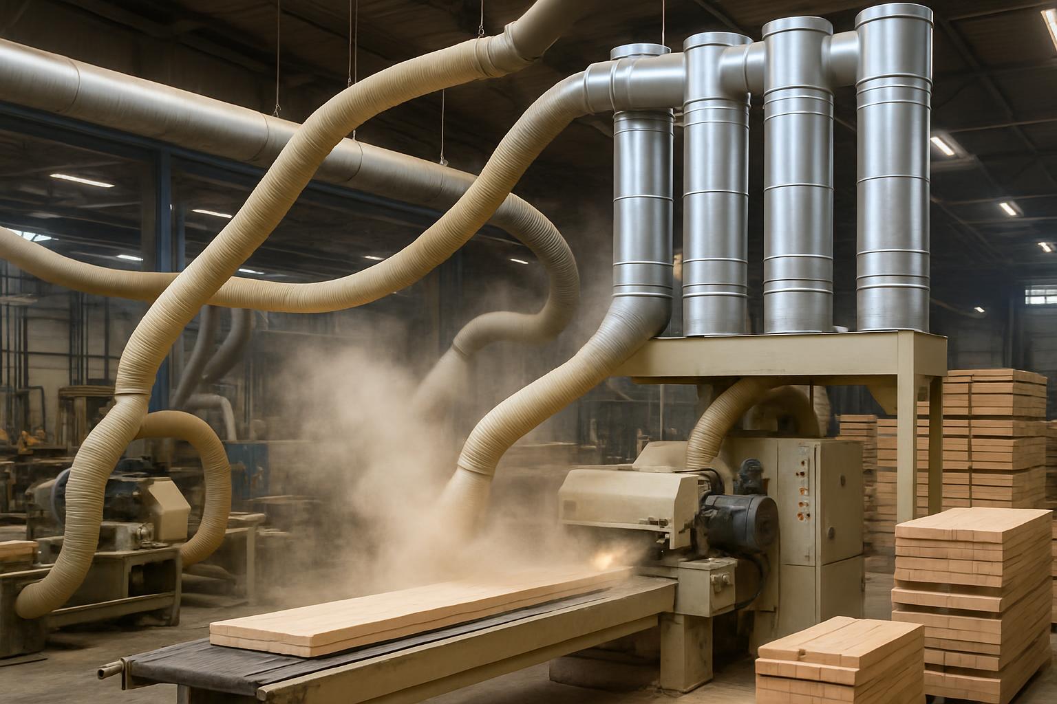
1. Context and Characteristics of Emission Sources from Domestic Wastewater Treatment Systems
Emissions generated in domestic wastewater treatment plants primarily come from upstream processes (screening, grit separation, equalization), biological zones (anaerobic, anoxic, aerobic), settling – disinfection tanks, and especially from the sludge subsystem (thickening, fermentation, dewatering). The gas mixture often contains unpleasant odors due to reduced sulfur compounds, ammonia, and volatile organic compounds; simultaneously, biogas such as methane and carbon dioxide may be present if anaerobic processes occur. These components cause corrosion, pose safety risks, and generate odor complaints, thus the design strategy should not only focus on equipment selection but also include solutions for collection, isolation of sources, and operational control to limit emissions at the source.
The relationship between wastewater technology and gas emissions is very direct. In anaerobic environments, microorganisms decompose organic matter to produce biogas consisting of CH4 and CO2; maintaining an influent pH of around 6.6–7.6 and distributing flow from the bottom at a velocity below 1 m/h (according to common configurations for anaerobic tanks) helps stabilize the process but also makes gas emissions more uniform, facilitating closed collection and centralized treatment solutions. In anoxic zones, DO conditions of approximately 0 mg/L need to be maintained for effective nitrate removal; at this point, gas release during mixing also needs to be controlled by covers and forced ventilation. Aerobic zones (aerotanks) create turbulence and carry odors away from the water surface, thus covering solutions, maintaining negative pressure, and selecting appropriate odor treatment technologies are mandatory requirements for projects near residential areas.
It is also important to note that high wastewater treatment efficiency means lower residual volatile solids in the effluent, leading to reduced odor intensity after the final stages. For example, aerobic processes can remove about 90% of BOD and reduce suspended solids by 97%, contributing to odor limitation in subsequent settling tanks. With appropriate anaerobic technology, COD removal can reach 80–90% before transitioning to aerobic stages, thereby transforming “odor” into recoverable “biogas”; this changes the perception of odor systems: instead of just treating at the end of the pipe, priority is given to reducing emissions at the source and harnessing energy.
Configurations such as SBR and MBR create specific gas emission patterns. SBR operates in batches of 4–8 hours, so odors/gases can be “concentrated” at the filling – aeration – drainage stages; conversely, MBR maintains very high MLSS (3,000–12,000 mg/L) so it is more stable in terms of odor but requires continuous gas release to protect the membrane. Therefore, the design of the emission system must align with the hourly operational graph, avoiding oversized conditions during off-peak hours or overload during peak hours.

2. Compliance Framework and Applicable Standards
For generated emissions, when collected and discharged through chimneys, facilities need to comply with the requirements of QCVN 19:2024/BTNMT issued under Circular 45/2024/TT-BTNMT. This standard is the basis for enterprises to determine the parameters that need to be monitored, arrange measurement lines, and serve as the basis for acceptance. For systems currently in operation, many places still refer to QCVN 19:2009/BTNMT during the transition phase, but new design directions should follow updated requirements to avoid having to retrofit twice.
In practical projects, local legal documents may require the scope of odor control at the facility boundary and specify periodic measurement regimes. Standardizing the chain: identifying sources – covering – forced ventilation – treatment – dispersion, along with a monitoring plan that complies with the above standards is a decisive factor that helps investors facilitate evaluation and operation.
3. Determining Load and Selecting Collection Schemes
The design of the emission system begins with “reading” the wastewater technology process. In anaerobic tanks, influent pH of 6.6–7.6 and bottom distribution at below 1 m/h not only ensure microbial growth but also allow for relatively stable predictions of CH4/CO2 release rates. This information determines the size of the cover, gas collection pipes, condensate traps, and fans. In anoxic zones (DO ≈ 0 mg/L), the mixing axis often causes gas entrainment, so local ventilation in the form of low hoods and adequate suction flow is necessary to maintain negative pressure, avoiding excessive suction that causes water splashing and equipment wear.
The aerobic zone is where odors are strongly diffused due to aeration. An effective solution is to cover the tank and divide suction zones according to “hot spots” (aeration head – tank end), directing gas to odor treatment clusters. In SBR tanks, due to the 4–8 hour cycle, suction flow can be programmed according to phases (increasing during filling/aeration, decreasing during settling/waiting). For MBR, continuous ventilation around the membrane module is necessary to prevent fouling; simultaneously, maintaining MLSS at 3,000–12,000 mg/L increases humidity and mist in the chamber, requiring droplet separation systems before odor treatment equipment.
The sludge area is a significant “emission point” due to secondary decomposition in thickening tanks, fermentation tanks, and dewatering machines. Isolating each dewatering machine with cabins, suctioning at the source, and passing gas through wet scrubbing – biological filtration or final adsorption is a common configuration. In anaerobic tanks, after separating solid – liquid – gas phases, the gas stream is directed through an alkaline solution (NaOH) to absorb impurities before recovery or treatment; this practice has been applied in anaerobic processes to reduce odor and protect downstream equipment.
3.1. Relationship Between Wastewater Treatment Technology and Gas Emissions
The AAO technology combining anaerobic – anoxic – aerobic allows for nutrient control while significantly converting organic matter right from the anaerobic stage (COD removal can reach 80–90%). This reduces odor loads in aerobic stages, but requires management of biogas safety and odors in the anaerobic chamber. In anoxic conditions (DO ≈ 0 mg/L), the phenomenon of “gas release” during mixing causes odors to accumulate under the cover, thus evenly distributing suction points along the tank is essential.
With Aerotank, BOD removal efficiency of about 90% and SS removal of about 97% significantly reduces odors in subsequent stages. However, strong diffusion during aeration increases surface emissions if not covered and forced ventilation is not applied. SBR combines multiple stages into one tank, creating peaks in emissions every 4–8 hours; the design must be “synchronized” with the cycle map to optimize fan size and filter material layers. Meanwhile, MBR, thanks to high MLSS of 3,000–12,000 mg/L and membrane separation of 0.1–0.4 µm, produces water that is almost free of SS and microorganisms, limiting odors in post-treatment facilities; however, the membrane area requires stable ventilation to maintain membrane cleanliness.
3.2. Input Data for Design from Actual Operations
A good emission design file needs to integrate the core operational parameters of the water system: influent pH and flow rate in the anaerobic tank (pH 6.6–7.6; flow rate below 1 m/h), target DO in the anoxic zone (approximately 0 mg/L), mixing – aeration ratios in Aerotank, 4–8 hour cycles of SBR, MLSS in MBR (3,000–12,000 mg/L), and membrane pore sizes (0.1–0.4 µm). These figures help estimate the required gas flow rate, humidity, mist content, and corrosive characteristics – thereby selecting materials, droplet separation systems, and appropriate treatment solutions.
Simultaneously, field surveys need to identify “odor hotspots”: garbage collection tanks, waste shredders, long retention time equalization tanks, sludge thickening chambers, sludge conveyors, sludge storage. Real-time data according to working shifts and technology phases (especially with SBR) allow for “shaping” odor/gas graphs to design the shortest pipeline, reducing pressure loss and lowering fan operating costs while maintaining stable negative pressure.
4. Suitable Odor and Biogas Treatment Technologies
There is no “one-size-fits-all” technology for every plant. Instead, the optimal configuration is often a combination: local collection – pre-treatment (droplet separation, wet scrubbing) – biological or chemical treatment – polishing adsorption – chimney dispersion. The choice depends on source characteristics, area, desired automation level, maintenance requirements, and long-term strategies (e.g., whether to utilize biogas or not).
In anaerobic stations, the biogas line needs to separate moisture, early H2S removal (e.g., through NaOH solution during anaerobic phase separation), and then be used or safely burned. The odor line from open tanks – dewatering machines is suitable for wet scrubbing – biological filtration – adsorption, due to its flexibility and reasonable operating costs.
4.1. Wet Scrubbing
Wet scrubbing is the first choice when odors contain soluble components or react well in solution, such as absorbing/removing H2S with alkaline solutions. In practice, during anaerobic processes, after phase separation, the gas mixture is directed through NaOH solution to absorb unwanted gases before being sent to subsequent tanks – this method can be expanded into independent wet scrubbers for odor lines. The advantages are stability, easy chemical control, and handling variable loads due to the “buffer” of the solution; the downside is the generation of wastewater and the need to manage formed salts.
When ammonia is predominant, scrubbers can be configured with acid solutions to absorb NH3. Before wet scrubbing, droplet separation/aerosol removal is always necessary to limit fine sludge and grease carryover, protecting the buffer material and nozzles. Controlling pH, monitoring recirculation flow, and periodic backwashing are key points to maintain long-term effectiveness.
4.2. Biological Filtration
Biological filtration utilizes microorganisms adhering to materials to oxidize odor-causing compounds. With the characteristic odors from domestic wastewater typically at medium and continuous loads, biological filtration or biotrickling filters are effective candidates if moisture, nutrients, and pH of the buffer layer are maintained appropriately. The design needs to ensure even gas distribution, control blockages due to dust – mist, and arrange wet pre-treatment stages when high H2S levels are present to avoid shock loads.
Biological filtration is suitable for open tank areas and odor lines from dewatering machines, where loads fluctuate according to working hours. The strengths are low operating costs and environmental friendliness; the weaknesses are sensitivity to toxic fluctuations, requiring systematic biological operation and “startup” time for the microbial layer.
4.3. Activated Carbon Adsorption
Adsorption is used as a polishing stage to capture residual compounds or handle short peak loads. The design should follow a two-stage series (lead–lag) to switch when saturated and avoid “leakage” of odors. The appropriate position is after wet scrubbing/biotrickling, when the gas has been dehumidified and impurities reduced, thus extending the lifespan of the carbon.
The limitation of adsorption is the cost of replacing carbon if used as the main facility for large loads; therefore, deploying it in localized areas with small flow rates, or as a final step for larger lines will be more effective. Monitoring pressure drop and total VOCs before/after the carbon cluster is a common operational monitoring method to proactively plan replacements.
4.4. Biogas Management from Anaerobic Processes
Biogas consisting of CH4 and CO2 from anaerobic tanks requires a separate line: covering the tank, collecting gas with corrosion-resistant pipes, separating moisture, early H2S treatment (e.g., contacting NaOH solution as applied in anaerobic phase separation), and then generating electricity, providing heat, or safely burning. Backfire prevention valves, condensate traps, and gas concentration monitoring systems are important protective layers for technology safety.
Odorous gases that do not contain CH4 (from open tanks, dewatering machines) need to be separated from the biogas line to avoid explosion risks. Two independent lines allow for separate optimization: the biogas line aims at energy recovery; the odor line focuses on maximum odor removal and safe dispersion.
5. Design of Collection – Partitioning – Airtight Systems
Effective collection starts from the surface of the tank: airtight covers, inspection ports with seals, suction points distributed according to strong emission areas, and maintaining adequate negative pressure to avoid leaks while not overly sucking to cause water splashing. Cover and pipe materials should prioritize composites, engineering plastics, or corrosion-resistant steel, due to the environment containing moisture, H2S, and NH3 being quite harsh.
The piping network needs to be optimized to reduce pressure loss: straight lines, limiting bends, and having periodic condensate discharge points. At the fan inlet, install droplet separators – de-misters to protect the blades and motor. Combining variable frequency drives for fans helps adjust according to cycles (especially with SBR), while maintaining stable negative pressure throughout the network. Each treatment cluster should have a safe bypass and sampling points before/after for convenient periodic checks.
6. Reduction Efficiency and Control Strategies
Odor reduction efficiency depends on controlling emissions at the source and selecting appropriate technology lines. When anaerobic processes are optimized (pH 6.6–7.6; distribution below 1 m/h), most organics are converted into biogas at the initial stage, reducing odor burdens for subsequent stages. In aerobic conditions, maintaining reasonable aeration – mixing regimes and good covering helps prevent surface dispersion; meanwhile, MBR with MLSS of 3,000–12,000 mg/L and membrane separation of 0.1–0.4 µm provides clean effluent, limiting odors at disinfection and final discharge.
In the odor treatment line, combining wet scrubbing before – biological treatment in between – adsorption after often yields stable results when loads fluctuate hourly. Maintenance schedules (buffer washing, chemical supplementation, droplet separator cleaning, carbon replacement) need to be linked with operational graphs, for example, increasing checks during hot seasons when odors are stronger. Measuring negative pressure at multiple points and recording community feedback helps adjust operations according to reality, not solely relying on inlet – outlet chimney indices.
7. Investment and Operating Costs: Components and Optimization Methods
Investment costs focus on the covering – piping network – fans – treatment equipment (wet scrubbers, biological filters, carbon towers). For anaerobic plants, the biogas line adds moisture separation equipment, early H2S treatment, and combustion or power generation systems. There is no “common price” for all projects; the economic optimization problem arises when designs are synchronized with existing wastewater technology, reducing pipe lengths, eliminating unnecessary suction points, and selecting equipment based on hourly load graphs rather than overly high assumed peak flows.
Operating costs mainly include electricity for fans and recirculation pumps, chemicals for wet scrubbing, makeup water, and consumables (buffer materials, activated carbon). The ability to operate safely – with minimal system downtime for “overhauls” is a decisive factor in total lifecycle costs. Synchronizing with the SBR 4–8 hour cycle to reduce suction flow during settling/waiting phases, or arranging pre-treatment of humid gas before passing through expensive materials such as carbon, are practical solutions that help reduce long-term costs.
8. Quick Comparison Table: The Impact of Wastewater Technology on Gas Treatment Options
| Wastewater Treatment Technology | Characteristics Related to Gas Emissions | Quantitative Parameters from References | Suggested Suitable Gas Treatment Lines |
|---|---|---|---|
| Anaerobic (in AAO or pre-treatment) | Emissions of CH4/CO2; strong odors at phase separation and input areas; need for fire safety | Influent pH 6.6–7.6; bottom distribution < 1 m/h; COD reduction up to 80–90% | Separate biogas collection; moisture separation; early H2S treatment (NaOH); utilization/burning; other area odors: wet scrubbing → biological filtration → carbon |
| Anoxic | Gas release during mixing; localized odors under the cover | Target DO ≈ 0 mg/L | Local suction hoods; wet scrubbing before biological filtration to stabilize loads |
| Aerobic (Aerotank) | Surface odor diffusion due to aeration; odor loads decrease when treatment efficiency is high | BOD removal ~90%; SS removal ~97% | Complete covering; negative pressure suction; biological filtration as primary; activated carbon polishing |
| SBR | Cyclic emission peaks; need to control fans according to phases | 4–8 hour cycle | Program fans according to phases; wet scrubbing to buffer load fluctuations; biological filtration/carbon afterwards |
| MBR | Stable odors in later stages; requires continuous ventilation in the membrane area | MLSS 3,000–12,000 mg/L; membrane pore size 0.1–0.4 µm; treatment efficiency increase of 10–30% | Fixed low–medium flow suction; pre-droplet separation; compact biological filtration; carbon polishing |
9. Project Implementation Process: From Survey to Acceptance
Starting with field surveys and “reading” the technology: identifying tanks – emission equipment, measuring existing wind pressure (if any), mapping operational cycles (SBR 4–8 hours, continuously aerated MBR, etc.). Collecting key quantitative parameters: influent pH and flow rate in the anaerobic chamber, target DO in the anoxic chamber, MLSS – membrane size in MBR, BOD/SS efficiency in the aerobic zone to forecast odor levels downstream. This data directly relates to the emission configuration: from selecting corrosion-resistant materials to fan sizes and types of treatment equipment.
After simulating flow rates and pressure losses, develop a covering plan – the shortest pipeline – droplet separation points – fans – treatment (wet scrubbing/biotrickling/carbon). Legal documentation should follow QCVN 19:2024/BTNMT (according to Circular 45/2024/TT-BTNMT) or QCVN 19:2009/BTNMT during the current transition phase at the local level, along with a monitoring plan. The trial phase needs to check for stable negative pressure, observe humidity – mist in pipes, adjust wet scrubbing chemical doses, monitor pressure drops in the buffer layer, and establish a maintenance schedule. Finally, acceptance should be based on meeting regulatory requirements and effective odor reduction at the facility boundary.
10. Frequently Asked Questions (FAQ)
1) Is it mandatory to collect all tanks in a closed manner?
Not necessarily. Prioritize covering and forced suction at “hot spots” such as anaerobic tanks, equalization, aerotanks, and dewatering machines. Tanks that achieve high treatment efficiency (e.g., aerobic BOD removal ~90% and SS ~97%) usually have less odor and can use controlled ventilation solutions instead of full enclosure.
2) When should wet scrubbing be chosen over biological filtration?
If odors contain soluble/removable components in solution (like H2S), or if odor loads fluctuate significantly by hour, wet scrubbing helps “buffer” and stabilize before moving to subsequent stages. Biological filtration is suitable when low operating costs and relatively stable loads are needed, and can be combined with prior wet scrubbing to enhance durability.
3) SBR causes cyclic odors, how to manage it without “oversizing” the fan?
Synchronize fan control according to the 4–8 hour operational phases, increasing flow during filling/aeration and reducing during settling/waiting. Adding buffer volume in the wet scrubber or biological filter helps absorb short peak loads without needing to maximize fan capacity.
4) Does MBR help reduce odors?
MBR maintains high MLSS (3,000–12,000 mg/L) and membrane separation of 0.1–0.4 µm, resulting in very clear effluent, with less SS and microorganisms, so odors in subsequent stages are usually lower. However, the membrane area needs stable ventilation to prevent fouling and control humidity – mist before passing through odor treatment equipment.
5) What line should be followed for treating biogas from anaerobic processes?
CH4/CO2 gas from anaerobic processes needs a separate line, covering the tank, separating moisture, and early H2S treatment (possibly using NaOH solution), then utilizing energy or safely burning. It is not advisable to mix with the regular odor line to avoid explosion risks and impact odor treatment efficiency.
6) Which standards should be referenced for emission chimneys?
For industrial facilities discharging emissions through chimneys, refer to QCVN 19:2024/BTNMT under Circular 45/2024/TT-BTNMT; in places still applying the transitional phase, QCVN 19:2009/BTNMT can be referenced. The choice of standards should be agreed upon early with the authorities to standardize design and monitoring plans.
Nanoen
NANO THANG LONG ENVIRONMENTAL COMPANY LIMITED
Hanoi Office: No. 15 TT18 Van Phu Urban Area, Ha Dong, Hanoi
Can Tho Office: 661E/29, Vo Van Kiet Street, Binh Yen A Area, Long Hoa Ward, Binh Thuy District, Can Tho City
Ho Chi Minh City Office: 533/12/7, Pham Van Bach Street, Ward 15, Tan Binh District, Ho Chi Minh City
Hotline: 0986.689.781 - 0969.054.226
Email: thanglongnanoen@gmail.com
Facebook: www.facebook.com/thanglongnanoen