1. Context, Legal Requirements, and Characteristics of Paint Dust
Paint dust primarily arises from two process groups: wet spraying (overspray creating solid mist with solvents) and electrostatic powder coating (dry fine particles). With wet paint, the volatile organic compounds (VOCs) pose risks of odor, fire safety, and corrosion, while the suspended solid particles require an effective dust collection system. For powder coating, the exhaust is typically dry, with a low dust load but a particle distribution skewed towards fine and ultrafine regions, necessitating high-efficiency and long-term stable filtration equipment.
Paint manufacturers and investors in emission treatment systems must ensure that exhaust gases comply with QCVN 19:2024/BTNMT regarding industrial emissions, where the total dust parameter is a core criterion when designing and accepting the system. In terms of technology, fabric bag filtration (bag filter) is widely chosen due to its high fine particle recovery efficiency and operational stability. However, VOCs from solvent-based paints cannot be treated by fabric bags; it is necessary to integrate odor/solvent vapor removal technology in the stage after dust collection (based on practical experience and market technology trends).
One characteristic to be aware of is that paint dust tends to adhere, easily forming “dust cakes” that are difficult to regenerate if operational parameters are incorrect, or if humidity/solvent phase in the exhaust is not controlled. Fabric bag filtration is only truly durable when core parameters such as filtration velocity, pressure drop, compressed air pressure, airflow, and bag material are correctly selected and adjusted to the characteristics of paint dust, rather than simply applying configurations from other industries.

2. Principles of Fabric Bag Dust Filtration and Key Components
2.1. Airflow – Fabric Bag – and the Role of “Dust Cake”
In a bag filter, the airflow carrying dust passes through the surface of the fabric bag, where dust particles are retained due to a combination of sieving, inertial impaction, diffusion, and microscopic adhesion forces. After a short period, the bag surface forms a stable “dust cake,” which acts as a secondary filter, significantly enhancing the ability to retain ultrafine particles. As a result, dust filtration efficiency can exceed 99% in most cases, even surpassing 99.5% for fine particles, according to industrial operational data.
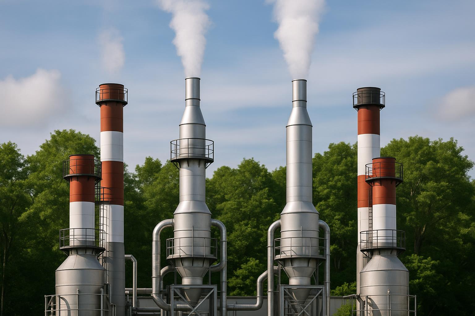
The clean air, after passing through the dust cake/filter bag, rises to the clean chamber and exits through the chimney. As the dust layer thickens, the pressure drop across the bag increases; the system will activate the regeneration mechanism (dust shaking) to restore airflow. If the regeneration is controlled properly, the filtration efficiency remains nearly constant over time, even when the dust load fluctuates.
2.2. Regeneration Mechanism with Compressed Air Pulses
With pulse-jet technology, a compressed air pulse at a pressure of about 5–7 bar is blown very briefly (about 100–200 ms) in the reverse direction, creating a pulse wave that dislodges the adhered dust layer and allows it to fall into the hopper. The advantage of pulse-jet is that it can clean continuously while the system is still filtering, suitable for 24/7 operations and fine dust loads like powder paint. The pulse duration and pressure are two important variables: too weak and it won’t clean thoroughly, too strong may fatigue the fabric fibers or excessively disturb the dust cake.
Besides pulse-jet, mechanical vibration or reverse air regeneration options are also present but are less suitable for paint spraying lines requiring stable airflow, due to the downtime needed for cleaning and limitations on the filtration coefficient. Therefore, choosing pulse-jet often provides a good balance between efficiency, operating costs, and flexibility.
2.3. System Structure and Air Tightness Requirements
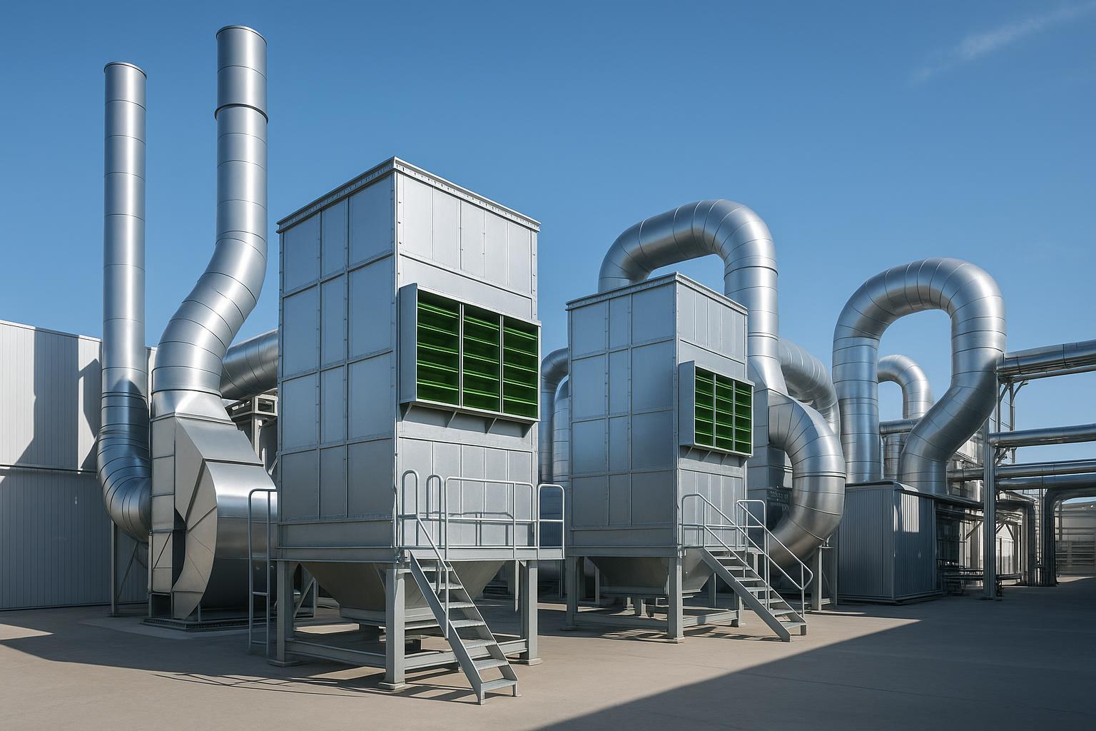
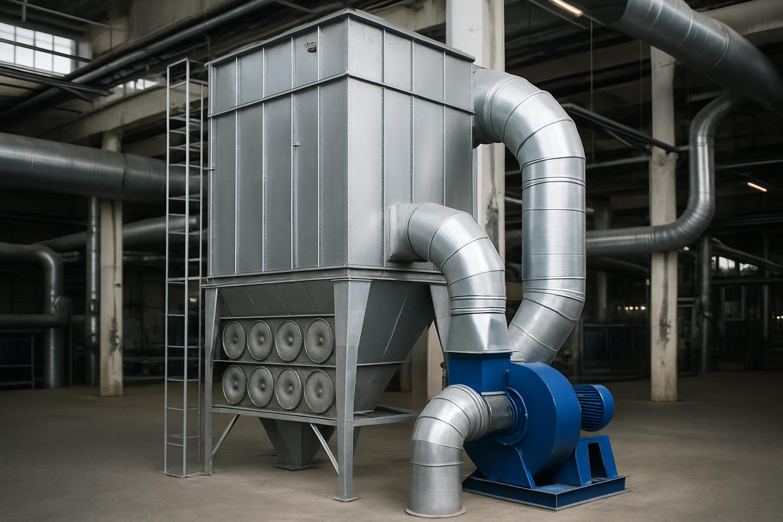
A complete system includes: a filtering chamber (dust chamber/clean chamber), filter bags and cages, pulse blowing pipes and solenoid valves, a compressed air tank, a central suction fan, inlet/outlet ducting, a dust hopper, and a discharge mechanism (rotary valve, screw conveyor), along with a control cabinet. Common filter bags are 2–6 m long, with a diameter of 120–160 mm; the structure of the filter chamber shell is made of thick enough steel plate to withstand vibration and working temperature, ensuring airtightness throughout the line from the suction hood to the chimney.
An inlet diffuser is usually arranged at the inlet to reduce the airflow velocity to below 1.5 m/s before contacting the filter surface, minimizing wear and allowing coarse dust to fall into the hopper. The dust hopper needs a minimum angle of about 55° to avoid adhesion, especially with paint particles that tend to be sticky when encountering moisture. The pressure drop measurement system across the bags is an essential sensor for automatically controlling the shaking cycle and alerting abnormalities.
3. Parameter Design for Paint Dust: From Airflow to Bag Material
3.1. Airflow, Dust Load, and Power Range
Design always starts from the actual airflow that needs to be processed at peak mode, then adds losses due to leaks/openings in the duct system and reserves for fluctuations. In industry, bag filter systems can operate flexibly from about 5,000 to 200,000 Nm³/h; choosing a modular configuration makes it easier to expand when increasing production or the number of spray chambers.
With paint spraying lines, the input dust load is usually lower than in crushing/impacting industries, but the particle distribution skews towards fine (including PM2.5). Therefore, the design prioritizes low to medium filtration velocities and sufficiently large filter surfaces to maintain reasonable pressure drops, minimizing clogging due to sticky dust.
3.2. Filtration Velocity and Target Pressure Drop
Filtration velocity (air-to-cloth) should be in the range of approximately 0.8–1.5 m/min for fine dust to ensure contact time and maintain efficiency. When the filtration velocity is too high, fine dust is difficult to retain stably, and the dust cake is strongly disturbed, leading to fluctuating pressure drops and increased fan consumption. Conversely, if too low, it makes the system bulky and unnecessarily increases investment costs.
Regarding pressure drop, the common operating range is approximately 800–1500 Pa, ideally maintaining around 1000–1400 Pa. When the pressure drop exceeds the design threshold, the fan capacity may need to increase by about 10–20%, resulting in higher electricity costs. Therefore, controlling dust shaking based on pressure drop (rather than fixed time) often helps save energy and stabilize operation.
3.3. Airflow Velocity in the Filter Chamber and Duct
At the inlet of the filter chamber, the velocity should be reduced by the diffuser to values below 1.5 m/s, allowing coarse particles to fall naturally into the hopper before colliding with the filter surface. Inside the filter chamber, the vertical airflow field needs to be stabilized; design experience suggests that the axial velocity should not be lower than about 1.0 m/s and should not exceed about 1.3 m/s to avoid dust settling in the chamber or re-entraining dust that has fallen.
Along the duct, the combination of the suction hood – collection duct – main duct must be balanced in airflow to limit “dead spots” and localized build-up. The airtightness of the entire system not only affects efficiency but also determines the output dust concentration, as “unloaded” suction will reduce velocity at the hood and the effectiveness of source collection.
3.4. Fine Paint Dust and Bag Material Selection
Bag filters can effectively capture a size range of approximately 0.1 to 10 µm if the material and filtration velocity are appropriately chosen. Powder paint dust is relatively dry and usually compatible with polyester bags under the material's temperature threshold. However, with wet spraying, moisture and solvent mist can make the dust cake sticky; it is necessary to consider membrane-coated bags, anti-adhesion treatments, or smooth surfaces to reduce the risk of clogging.
Typical temperature limits by material: below about 150°C can use PP, polyester, or acrylic; in the range of about 150–220°C, prioritize PPS or aramid (Nomex); above about 220°C, consider fiberglass, FMS, or PTFE. Although paint exhaust is usually below 100°C, selecting the right material is still important as solvents/chemical vapors can affect the bag's lifespan if incompatible.
3.5. Hopper Design and Dust Discharge Mechanism
The dust hopper needs a minimum angle of about 55° to ensure self-flow, minimizing the formation of “dust bridges.” The bottom of the hopper can be equipped with a rotary valve or screw conveyor for continuous discharge, preventing dust from re-entering the filter chamber, especially when the shaking cycle occurs frequently. For powder paint dust that can be reused, a separate recovery point should be arranged from mixed or dirty dust to manage quality.
In VOC-containing paint environments, integrating explosion-proof valves/pressure relief doors and grounding against static electricity is a notable safety requirement. Placing fire detection sensors on the inlet duct or filter chamber helps detect ignition sources early, even when this risk is not as high as in the wood industry.
4. Integration with Painting Lines: Pre-Treatment and Technology Limits
4.1. Dry/Wet Spray Booth and Coarse Particle Pre-Treatment
In wet paint spraying lines, the wet spray booth uses water/mist membranes to retain excess paint particles, but the resulting water needs treatment. Meanwhile, the dry spray booth uses primary filter materials like cotton/filter paper to capture larger particles, helping reduce the load on the fabric bags in the fine stage. This combination is suitable when optimizing bag lifespan and minimizing clogging due to wet/sticky particles is necessary.
For electrostatic powder coating, a cyclone can be arranged upstream to recover particles >10 µm for reuse, followed by a bag filter for fine and ultrafine particle retention. Cyclones are effective with medium-large particles but are not suitable for dust <5 µm, thus cannot replace fabric bags if low and stable output concentration is required.
4.2. VOC and Odor: Treatment Limits of Fabric Bags
Fabric bag filtration cannot treat solvent vapors and the characteristic odors of solvent-based paints. After collecting solid particles, the airflow may still contain VOCs and requires separate treatment technology (e.g., activated carbon layers or other specialized solutions depending on the technical problem). The correct sequence is: dust collection – dust filtration – then VOC treatment if necessary, rather than forcing the fabric bag to handle both functions.
In practice, clearly separating treatment stages not only enhances operational reliability but also helps businesses meet stricter emission requirements according to QCVN 19:2024/BTNMT for dust, while also creating a foundation for integrating appropriate VOC removal technology if the use of solvent-based paints is mandatory.
5. Performance, Output Concentration, and Quick Calculation Examples
5.1. Filtration Efficiency and Output Dust Concentration
Bag filters have been recorded to achieve efficiencies above 99% in most industrial cases; with optimal configurations, the system can recover ultrafine particles (including PM2.5) and maintain output dust concentrations at around 10–20 mg/Nm³. This concentration range helps businesses proactively meet stringent total dust requirements in emissions, especially when the source is fine paint particles.
The stability of performance strongly depends on controlling dust shaking based on pressure drop. When the pressure drop remains stable in the range of about 1000–1400 Pa, the system typically maintains consistent airflow, stable dust cakes, and does not experience sudden increases in fan power consumption. Fluctuations exceeding 1500 Pa are an early signal to reconsider the pulse cycle, pulse pressure, or moisture/stickiness conditions on the bag surface.
5.2. Example Calculation of Filter Area and Number of Bags
Assuming a system needs to process 30,000 m³/h. Converting to minutes gives 500 m³/min. If selecting a design filtration velocity of 1.2 m³/m²/min, the required filter area is approximately 416.67 m². With bags of 160 mm diameter and 6 m length, the area of each bag is about 3.01 m². Therefore, the number of bags needed is around 138–140 bags. This is a preliminary calculation to visualize the scale; when implementing in detail, additional factors such as duct losses, safety factors, and the adhesive properties of paint dust should be considered.
At the optimization stage, engineers will review the airflow distribution ratio between compartments, the height of the filter chamber to maintain axial velocities in the range of about 1.0–1.3 m/s, and also arrange the diffuser to keep the inlet velocity below 1.5 m/s. These limits help reduce bag wear and prevent dust from circulating in the chamber.
6. Investment and Operating Costs: Technical “Levers” for Optimization
6.1. Cost Components and Impact of Pressure Drop
The total investment cost of the fabric bag filtration system comes from the filter body, bags and cages, fans, compressed air system – pulse valves, ducting, dust discharge mechanisms, and automation. In the operational lifecycle, electricity costs for fans and compressed air account for a significant proportion, followed by periodic bag replacements. Real-world data shows that bag replacement costs can account for about 20–30% of the total ownership costs of the system, so choosing the right bag material and designing to keep the operating pressure drop within a reasonable range are two effective financial “levers.”
When the pressure drop exceeds the design threshold, the fan capacity may need to increase by about 10–20%, leading to higher electricity costs. This often arises from excessively high filtration velocities, inappropriate dust shaking, or moisture/solvents causing sticky dust cakes. Optimizing the pulse cycle based on pressure drop, controlling the dryness of compressed air, and using a good diffuser from the start are ways to sustainably reduce OPEX.
6.2. Suggested Configurations to Reduce Lifecycle Costs
For powder coating lines, combining a cyclone to collect dust >10 µm before entering the bag filter helps reduce the load on the filter surface, allowing for lower filtration velocities and pulse frequencies, thus increasing bag lifespan. In wet paint lines, a dry spray booth pre-treating large particles before fine filtration with fabric bags also yields similar effectiveness, especially when the bag surface is treated smooth/anti-adhesion to cope with paint mist.
At the detailed level, maintaining a target pressure drop of around 1000–1400 Pa, pulse pressure of 5–7 bar, and pulse duration of 100–200 ms usually provides a good balance between compressed air consumption and bag surface cleanliness. Controlling the inlet velocity below 1.5 m/s helps minimize wear, thereby reducing bag replacement costs – which can account for 20–30% of total ownership costs as mentioned.
7. Considerations in Construction, Installation, and Safety
7.1. Ducting, Suction Hoods, and Leak Testing
Construction of ducting should prioritize uniform losses, avoid sharp bends, ensure airtight joints, and include access doors for cleaning. The suction hood in the spray booth must cover the emission area, with a minimum suction flow according to the factory's internal standards and balanced between suction points to avoid “air competition.” Before trial runs, the entire line needs to be leak tested to eliminate leaks – a common cause of pressure drop fluctuations and reduced source collection efficiency.
For powder paint, a pre-treatment cyclone should be arranged close to the source for recovery and reuse. In wet paint, a primary dry filter layer right in the booth helps reduce sticky dust entering the bags. Regardless of the configuration, clearly delineating “dirty/clean” areas in the layout and waste flow is a requirement for safe, clean operation and to avoid re-dispersion.
7.2. Compressed Air, Electricity – Control and Fire Safety
The compressed air supplied to the pulse valves must be dry and clean to avoid moisture accumulation in the blowing pipes, which is particularly important for paint dust that is moisture-sensitive. The control system needs to integrate pressure drop sensors to activate shaking based on actual load and alert when exceeding 1500 Pa. The control cabinet should support event history to allow engineers to trace back any anomalies in pulse pressure, airflow, or bag drops.
Regarding safety, when handling dust with VOCs or static electricity risks, it is necessary to ground the entire frame, bag cages, and ducting; consider bags with anti-static features. Properly orienting explosion-proof valves/pressure relief doors and installing fire detection sensors on the inlet line, especially before dry seasons, are small construction details but have a significant impact on the risk of unscheduled machine downtime.
8. Quick Comparison of Dust Filtration Technologies Applicable to Paint Dust
| Technology | Typical Efficiency | Suitable Particle Size Range | Typical Output Dust Concentration | Technical Notes |
|---|---|---|---|---|
| Fabric Bag Filtration (Bag Filter) | ≥99% to >99.5% (optimized for fine particles) | ~0.1–10 µm | ~10–20 mg/Nm³ | Operating pressure drop ~1000–1400 Pa; filtration velocity ~0.8–1.5 m/min; suitable for powder paint, fine filtration after dry spray booth/cyclone. |
| Electrostatic Precipitator (ESP) | Up to ~99% with ultrafine dust | Especially good with very fine particles; electric field ~30–100 kV | Depends on design | High investment – operating costs; requires static electricity safety control when VOCs are present. |
| Cyclone (Centrifugal) | Good for coarse dust | Effective >10 µm; not suitable <5 µm | Depends on load and geometry | Suitable for pre-treatment/recovery of powder paint for reuse; does not replace fine filtration. |
9. Typical Application Cases by Paint Type
9.1. Electrostatic Powder Coating
Suggested technology chain: cyclone to recover particles >10 µm for reuse, then bag filter for fine dust to achieve concentrations of ~10–20 mg/Nm³. Filtration velocity should prioritize the lower end (around 0.8–1.0 m/min) if the product has many fine particles, reducing pulse frequency to extend bag lifespan. Arrange a 55° hopper with a rotary valve for continuous discharge to avoid re-entrainment and ensure the quality of recovered dust.
Bag materials can be smooth-coated polyester or membrane to reduce adhesion, with galvanized/stainless steel cages to prevent rust. Maintain pulse pressure at 5–7 bar and pulse duration of 100–200 ms; shake based on pressure drop to allow the system to adapt when dust loads increase/decrease during production shifts.
9.2. Wet Spraying (Water-Based/Solvent-Based)
Suggested configuration: dry or wet spray booth to capture coarse particles at the source, followed by a bag filter for the remaining particles; concurrently, design a branch line to treat VOCs/odors after dust collection. Due to solvent mist/moisture, prioritize bags with smooth/anti-adhesion surfaces, controlling dry clean compressed air to avoid bag stickiness.
In cases of high VOCs, it is mandatory to clearly separate tasks: fabric bags for solid particles – specialized technology for VOCs. Forcing the odor removal task onto the filter bags will be ineffective and will quickly increase pressure drop, raising electricity and bag replacement costs.
10. Project Implementation Process: From Design to Acceptance
10.1. Design – Assessment
Step 1: determine airflow (peak shift), dust load (particle distribution), adhesion/moisture characteristics, solvent composition. Step 2: select target filtration velocity of 0.8–1.5 m/min, calculate filter area, number of bags, and filter chamber structure to maintain axial velocity ~1.0–1.3 m/s; add a diffuser to keep inlet velocity below 1.5 m/s. Step 3: select bag material based on temperature/chemicals; pulse-jet shaking method (5–7 bar, 100–200 ms); hopper configuration ≥55° and dust discharge mechanism.
Step 4: coordinate pre-treatment (cyclone/dry/wet spray booth) and VOC treatment line if applicable. Step 5: calculate fan based on total system resistance (operating pressure drop 1000–1400 Pa), reserve for increased airflow when expanding the line. Prepare a monitoring plan for output dust concentrations at the target level of ~10–20 mg/Nm³ and control pressure drop at 800–1500 Pa during trial runs.
10.2. Construction – Trial Run – Handover
Mechanical construction should focus on airtightness and synchronization between the suction hood – collection duct – filter chamber – fan – chimney. Check the quality of compressed air (dry/clean) before connecting the pulse system. Install pressure drop sensors, pulse valves, control cabinets, and adjust shaking logic based on pressure drop. Integrate grounding, explosion-proof valves/pressure relief doors, and fire detection sensors according to safety recommendations.
Conduct trial runs following a load increase path, monitoring pressure drop across the bags, temperature, dust discharge status, and air leaks. Adjust pulse duration/pressure to maintain stable pressure drop in the range of 1000–1400 Pa. Acceptance should aim for long-term operation: stable output dust concentration of ~10–20 mg/Nm³, harmonious dust shaking system, no unusual vibrations, and no localized dust accumulation at the inlet duct/hopper.
11. Frequently Asked Questions (FAQ)
1) Can fabric bag filtration treat odors and VOCs from solvent-based paints?
No. Fabric bags only retain suspended solid particles. For VOCs/odors, a separate treatment step is needed after dust filtration, such as through adsorption layers or other specialized solutions depending on the technical problem.
2) What should the filtration velocity be for fine paint dust?
Operational experience shows that a range of about 0.8–1.5 m/min is suitable for fine dust. At the lower end of this range, the system is more stable with very fine particles or when there is a risk of stickiness.
3) How should the pulse pressure and duration for dust shaking be adjusted?
It is suggested to set the pulse pressure at around 5–7 bar and pulse duration at 100–200 ms. Setting shaking based on pressure drop will automatically optimize the cycle when dust loads change, reducing compressed air consumption and avoiding excessive shaking.
4) What output dust concentration can be expected?
With optimal configurations, bag filters can maintain concentrations around 10–20 mg/Nm³. To achieve this level stably, attention must be paid to airtightness, inlet velocity below 1.5 m/s, and pressure drop-based shaking control.
5) How often should filter bags be replaced?
The lifespan of bags is typically around 18–36 months, depending on the material, dust characteristics, and operating conditions. Throughout the system's lifecycle, bag replacement costs can account for about 20–30% of total ownership costs, so it is essential to choose the right material and maintain good pressure drop control.
6) When the pressure drop increases unusually, what should be checked first?
Check the dryness – cleanliness of the compressed air, the operational status of the pulse valves, and the pressure drop sensors. Also, review the filtration velocity, moisture/solvent conditions at the inlet, and the potential stickiness causing clogging on the bag surface.
Nanoen
NANO THANG LONG ENVIRONMENTAL COMPANY LIMITED
Hanoi Office: No. 15 TT18 Van Phu Urban Area, Ha Dong, Hanoi
Can Tho Office: 661E/29, Vo Van Kiet Street, Binh Yen A Quarter, Long Hoa Ward, Binh Thuy District, Can Tho City
Ho Chi Minh City Office: 533/12/7, Pham Van Bach Street, Ward 15, Tan Binh District, Ho Chi Minh City
Hotline: 0986.689.781 - 0969.054.226
Email: thanglongnanoen@gmail.com
Facebook: www.facebook.com/thanglongnanoen